


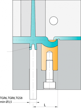
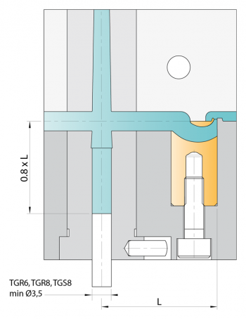
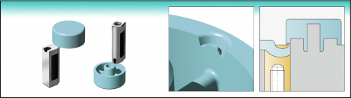
Tunnel gate inserts version S2 can be installed directly. You drill the hole - we supply the proper tunnel gate insert.

The gate point diameter of tunnel gate inserts "Standard" is already completely constructed. Due to the special manufacturing method all gate point diameters from 0,6 to 2,8 are clearly reproducible.
The chart shows the shot weights which can be reached with the respective sizes depending on the viscosity of the plastic materials used.
| TGR 6 | TGR / TGS 8 | TGR / TGS 10 | TGR / TGS 12 | TGR / TGS 14 | |
|---|---|---|---|---|---|
| Name | TGR 6 | TGR / TGS 8 | TGR / TGS 10 | TGR / TGS 12 | TGR / TGS 14 |
| Anschnitt | 0.6 | 0.6 / 0.8 | 0.8 / 1.2 / 1.6 | 1.2 / 1.6 / 2.0 | 1.6 / 2.0 / 2.4 / 2.8 |
| Ø Kanal | 2.5 | 3 | 4 | 5 | 6 |
| NV* | 3 | 5 | 30 | 50 | 200 |
| MV* | 2 | 4 | 20 | 35 | 120 |
| HV* | 1 | 3 | 12 | 25 | 75 |
* max. shot weights (g) | NV: low viscosity | MV: medium viscosity | HV: high viscosity
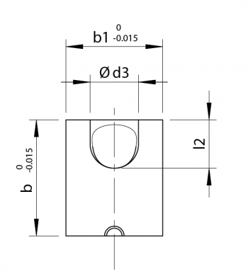
| Name | b | b1 | d1 | d2 | d3 | h | h1 | h2 | l1 | l2 | M | Version | |
|---|---|---|---|---|---|---|---|---|---|---|---|---|---|
| TGS8 | TGS8 | 8 | 6 | 0.6 / 0.8 | 1.9 /2.1 | 3 | 22.0 | 0.6 | 1.1 | 13 | 3.25 | 4 | S2 |
| TGS10 | TGS10 | 10 | 8 | 0.8 / 1.2 / 1.6 | 2.2 / 2.6 / 3.0 | 4 | 22.0 | 0.8 | 1.2 | 12 | 4 | 5 | S2 |
| TGS12 | TGS12 | 12 | 10 | 1.2 / 1.6 / 2.0 | 2.6 / 3.0 / 3.4 | 5 | 22.0 | 0.8 | 1.4 | 11 | 5 | 5 | S2 |
| TGS14 | TGS14 | 14 | 12 | 1.6 / 2.0 / 2.4 / 2.8 | 3.0 / 3.4 / 3.8 / 4.2 | 6 | 22.0 | 0.8 | 1.6 | 10 | 6 | 6 | S2 |
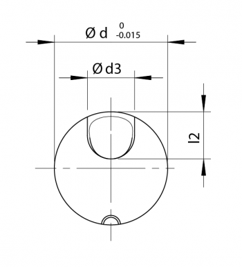
| Name | d | d1 | d2 | d3 | h | h1 | h2 | l1 | l2 | M | Version | |
|---|---|---|---|---|---|---|---|---|---|---|---|---|
| TGR6 | TGR6 | 6 | 0.6 | 1.9 | 2.5 | 17.0 | 0.6 | 0.8 | 10 | 2.5 | 4 | S2 |
| TGR8 | TGR8 | 8 | 0.6 / 0.8 | 1.9 / 2.1 | 3 | 22.0 | 0.6 | 1.1 | 13 | 3.25 | 4 | S2 |
| TGR10 | TGR10 | 10 | 0.8 / 1.2 / 1.6 | 2.2 / 2.6 / 3.0 | 4 | 22.0 | 0.8 | 1.2 | 15 | 4 | 5 | S2 |
| TGR12 | TGR12 | 12 | 1.2 / 1.6 / 2.0 | 2.6 / 3.0 / 3.4 | 5 | 22.0 | 0.8 | 1.4 | 11 | 5 | 5 | S2 |
| TGR14 | TGR14 | 14 | 1.6 / 2.0 / 2.4 / 2.8 | 3.0 / 3.4 / 3.8 / 4.2 | 6 | 22.0 | 0.8 | 1.6 | 10 | 6 | 6 | S2 |
| Name | TPE, TPU etc. | PE, PP, PET etc. | PC/ABS, PA, POM, HI-PC etc. | PA+GF, PC, SAN, PMMA etc. | |
|---|---|---|---|---|---|
| TGR 6 | TGR 6 | 9-12 | 12-18 | 15-22 | 18-25 |
| TGR/TGS 8 | TGR/TGS 8 | 11-14 | 15-22 | 19-27 | 23-30 |
| TGR/TGS 10 | TGR/TGS 10 | 15-18 | 19-27 | 24-33 | 28-36 |
| TGR/TGS 12 | TGR/TGS 12 | 18-22 | 22-30 | 27-36 | 32-40 |
| TGR/TGS 14 | TGR/TGS 14 | 20-25 | 25-33 | 30-37 | 35-43 |
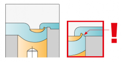
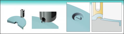
For optimum degating (especially of flat parts) we recommend the use of a companion vestige supplementing the vestige with cutting edge. This configuration will ensure that the part is separated from the runner flush with the parting line. Users will find this particularly advantageous in cases where materials are susceptible to stringing.
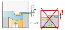
If the molded part is very thin, the vestige must be ground down. (t1>t/2)


Bitte werfen Sie auch ein Blick auf unsere nachstehenden Angebote.


i-mold is your competent partner for all questions about injection molding technology. Feel free to contact us!
